Special Series On Current-Mode Control
by Dennis Feucht of Innovatia Laboratories, Cayo, Belize
Peak or valley current control of switching converters is well established in engineering practice. Yet the irony of current-loop control is that, after decades, its theory is still undergoing refinement. This is the result, in part, of the complexity of the seemingly simple current-loop controller circuit. Its typical circuit diagram has few parts, yet the current-feedback loop is nonlinear and switched, having discrete-time behavior. This seven-part series, “Current-Loop Control In Switching Converters,”* reviews the history of current-loop control theory (i.e. how to accurately model current-mode control.) These articles attempt to clarify established concepts, identify problems with the existing theories or models of current-mode control, and then offer what might be the first truly unified model of current control, which is dubbed the “refined model”. In this section, abstracts and links for each of the articles in the series are provided below.
* Originally, published in the September 2011 through March 2012 issues of the How2Power Today newsletter.
Part 1: Historical Overview
Here in part 1, the author reviews the previous work done in modeling current-mode control using waveform-based approaches. These include work by Erickson and Macsimović; Ridley; Tymerski and Li; Tan and Middlebrook; Hong, Choi and Ahn; and Holloway and Eirea. The author also discusses Sheehan's circuit-based modeling. Following this historical review, the author discusses subtleties in the waveform-based models and how they are relevant to the development of the "ultimate waveform-based model" of current-mode control, which the author aims to develop in this series.
Part 2: A Waveform-Based Model
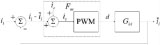
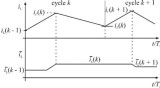
In part 2 of this article series on current-loop control, we continue to lay the groundwork for the development of a waveform-based model by deriving time-domain expressions for inductor current that describe the closed-loop converter behavior without introduction of slope compensation into the PWM block. We then derive the equations relating inductor current slopes to converter parameters under steady-state operation. These slope equations allow us to analyze the effect of small changes that occur from cycle to cycle and are of interest in incremental (small-signal) and linear analysis.
Part 3: Waveform-Based Model Dynamics
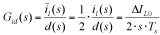
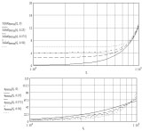
In this article, development of a unified model of current-mode control continues with the derivation of the dynamic equations for transfer functions of blocks in the current loop. Here in part 3, the author transforms the discrete-time equations from part 2 to the z-domain and pass quickly through it to the sampled s-domain. Conversion of the waveform equations to the z-domain is straightforward and lets the author derive a closed-loop transfer function of the peak-current controller. Dynamics equations are derived for both the valley-current samples and for the average inductor current for each switching cycle. By deriving the transfer functions for the average current, a new refined model begins to emerge that shows a somewhat different response than the familiar valley-current model.
Part 4: Clarifications Of Existing Models
The progression of models, from the low-frequency averaged model through Ridley’s sampled-loop model and on to Tan and Middlebrook’s effort to unify them in the unified model will continue in part 5 of this article series in the refinement of the unified model, the refined model. But here in our part 4 discussion of current-mode control, we digress in our derivation of a unified model by taking a closer look at the existing models. The goal here is to obtain a better understanding of the various current-loop models by uncovering the similarities among these models as well as some of their underlying assumptions. These concepts set the stage for explaining the refined model of current-mode control that will be presented in part 5.
Part 5: Refined Model
Previous sections of this article have discussed the historical development of the various models of current-mode control, compared and contrasted those models, and derived various expressions that lay the groundwork for developing a refined version of the unified model originated by Tan and Middlebrook. Here in part 5, the author presents his refined model of current-mode control that overcomes some of the limitations of the existing models that have been previously discussed.
Part 6: Slope Compensation
The previous installment of this article presented a refined model of current-mode control that provides a deeper unification of the quasi-static or low-frequency current-loop behavior with the sampling aspects by deriving the dynamics equations for transfer functions from the average current variable rather than the valley current. Here in part 6, the effect of slope compensation is included in the refined model. Specifically, this article analyzes the impact of three different slope-compensation schemes on the refined model, noting similarities and differences in the key waveform equations. It also notes how the refined model with slope compensation compares to earlier models of current-mode control. Finally, this article examines the implications of this analysis in terms of establishing guidelines for converter design that ensure loop stability.
Part 7: Fm0 In Models
This article on modeling of current-mode control concludes with a discussion of the PWM factor, Fm0. The refined model of current-mode control presented in part 5 is shown to be compatible with the major existing models when their limiting assumptions are factored in. This discussion refers back to expressions for the three slope-compensation methods derived in part 6. Finally, this lengthy process of modeling the current-loop ends by discussing the advantages and limitations of waveform-based models versus circuit-based models, and why it would be desirable to merge these two approaches.
The abstracts and links for the articles in the “Current-Loop Control In Switching Converters” series are also available as a PDF.
For further reading on power supply control methods, see the How2Power Design Guide, locate the “Design Area category” and select “Control Methods”.