 |
|
IN THIS ISSUE:
» Current Mode-Controlled DC-DC Regulators (Part 1): A Review Of Small-Signal Behavior
» Using VNA Software To Build Measurement-Based Models
» Output Filter Capacitor Size Depends On Inductor Value
» Focus On Magnetics:
Designing An Open-Source Power Inverter (Part 21): Converter Inductor Winding Design
» Book Review:
Book Aims To Demystify Power Supply Control
» Power Products
» Industry Event
» Other Top Power News
From the Editor's Desk David G. Morrison
Editor, HOW2POWER TODAY

Technical articles that discuss theory of operation and design principles tend to be “evergreen” as their information remains relevant for the many new engineers who are approaching the subject matter for the first time, or those who want a refresher. However, even these articles lend themselves to updates as there are always additional aspects that can be discussed, new ideas to be considered, and more recent application requirements to be addressed. A case in point is Tim Hegarty’s new series on current-mode control—part 1 appears in this newsletter. This article represents an update to a two-parter Tim wrote in 2014, where he explained the principles of current-mode control and details of its implementation, particularly its slope compensation. This series has remained popular with engineering readers over the years. However, with his new articles on current-mode control, he fills in additional details on modeling of the current and voltage control loops, citing some of the more recent works on the subject. Tim also sets the stage for introduction of a novel implementation of current-mode control in a CC-CV design. Another form of modeling comes into play in the work by Charles Hymowitz, Paul Ho and Michael LaNovara. They explain how to use a new software feature in a popular Vector Network Analyzer family to create accurate measurement-based models for simulation, particularly SPICE models, of passive components, sensors, filters, VRMs and other elements whose impedance can be measured. This November issue also presents Gregory Mirsky’s explanation of how to specify capacitance value and capacitor size for output filters in buck and bridge topologies, and Dennis Feucht’s discussion on inductor winding design in his open-source power inverter series. We hope you enjoy these items along with the latest power component and industry news.
|
|

|
HOW2POWER EXCLUSIVE DESIGN ARTICLES 
|
Current Mode-Controlled DC-DC Regulators (Part 1): A Review Of Small-Signal Behavior
by Timothy Hegarty, Texas Instruments, Phoenix, Ariz.
With simple operation and dynamics, current-mode control requires two loops: a wide-bandwidth inner current loop and an outer voltage regulation loop. Commonly used forms of current-mode control include peak, valley, average, hysteretic, constant on-time, constant off-time and emulated. Each technique offers certain advantages and trade-offs depending on the design requirements. This article, part one of a multipart series, represents an update to a previous series the author wrote in 2014 with more focus on the inner current loop. This part lays the groundwork for a subsequent article that details a cohesive implementation for a constant-current constant-voltage (CC-CV) circuit with two loops using a shared network for compensation. Part 1 begins with an overview of the small-signal behavior in fixed-frequency, naturally sampled, peak current-mode, pulse-width modulated (PWM) dc-dc regulators. Read the article…
|
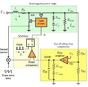
After reviewing the operating principles
of peak (shown here) and valley current-mode
architectures, the author reviews the
small-signal behavior of the inner current
loop and outer voltage loop. |

|
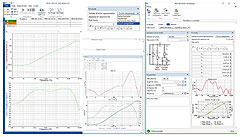
In this article, impedance measurements
are taken with a VNA on a set of capacitors,
a power inductor, and a ferrite bead. The
Bode Analyzer software suite is then used
to curve fit the data to SPICE models. |
Using VNA Software To Build Measurement-Based Models
by Charles E. Hymowitz, Paul Ho and Michael LaNovara, AEi Systems, Centennial, Colo.
In today’s power integrity (PI) simulations picohenries matter. Timely availability, fidelity, and model accuracy matter. However, vendor-supplied component models, including those available for passive and other components, are often inaccurate or not available. For system designers performing PI simulations, the answer to this problem is either to obtain better models from third-party sources or to build their own measurement-based models. This second option has been made easier by the new Curve-Fitting–Simulation Model generation feature in the Bode Analyzer software Suite (BAS). The BAS software drives the popular OMICRON Lab Bode 100 and 500 vector network analyzers (VNAs) and with the new model generation feature, this software can curve fit the data from impedance measurements to create lumped element models (SPICE). Read the article…
|

Output Filter Capacitor Size Depends On Inductor Value
by Gregory Mirsky, Design Engineer, Deer Park, Ill.
Typically, in an SMPS, the value of output filter capacitance is calculated based on the desired output ripple voltage and the assumed ripple current for a given inductor under the given set of operating conditions. However, this approach ignores the interplay between the capacitor and inductor in filtering the ripple current. What results is a non-optimum capacitor selection, both in terms of capacitance value and capacitor size. In this article we will define both the electrical and physical sizes required of a capacitor used for filtering the current ripple in a converter and decide whether this capacitor can handle the ripple current while working in the output filter. To do this, we’ll analyze operation of the output filter components in a simple buck converter power stage. Read the article…
|
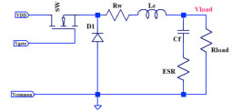
This analysis of output filter
capacitor requirements can be applied
to any buck or bridge topology. |

 |

|


FOCUS ON MAGNETICS 
Sponsored by Payton Planar Magnetics
A monthly column presenting information on power magnetics design, products, or related technology |
Designing An Open-Source Power Inverter (Part 21): Converter Inductor Winding Design
by Dennis Feucht, Innovatia Laboratories, Cayo, Belize
As this series moves forward, we explore the Volksinverter’s battery converter stage further, continuing the design of the inductor of the boost push-pull (BPP) transfer circuit. A two-winding coupled inductor, the boost or common-active (CA) PWM-switch inductor is the only power-transfer component (along with the fuse and connectors) that is in series with the battery and conducts the most current of all the Volksinverter circuitry. The procedure for magnetic component design begins logically with the magnetic design — the design associated with the core — for without it, there is nothing on which to base the winding (electrical) design. The previous part in this series presented the magnetic design, establishing key parameters such as Lmin, the minimum inductance needed for current protection; Lmax, the maximum inductance and energy storage (or transfer power) value at Igmax and Nmax; and Nw, the maximum turns that fit the core window.
Read the article…
|

 |
 |

 |

|

 |

|

BOOK REVIEW
 |
Book Aims To Demystify Power Supply Control
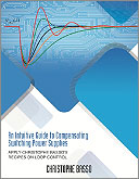
An Intuitive Guide to Compensating Switching Power Supplies, Christophe Basso, Faraday Press, Stairway Press, 2024.
Reviewed by Dennis Feucht, Innovatia Laboratories, Cayo, Belize
Author Christophe Basso has designed converter control ICs for ON Semiconductor (now called onsemi) in Toulouse, France and has written related books reviewed in How2Power Today. The preface of this manual neatly summarizes the problem it addresses: “… when teaching seminars, designing the control loop often comes back as the most difficult issue encountered by engineers. The theory is usually well understood but the implementation of what is described in textbooks is lacking in practical details, often unique to the specific control scheme. Many converters are stabilized by trial-and-error then shipped without the assurance that the product will remain stable during its operating lifetime.” Read the full story…
|
 |


POWER PRODUCTS  |

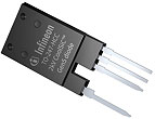
Infineon Technologies’ CoolSiC
Schottky diode 2000-V G5 family. |
2000-V SiC Schottky Diodes Raise Efficiency For DC Link Systems
 Photo: This product family offers the first discrete SiC diodes on the market with a breakdown voltage of 2000 V, according to the vendor. The diodes are suitable for applications with dc link voltages up to 1500 V and offer current ratings from 10 to 80 A. Photo: This product family offers the first discrete SiC diodes on the market with a breakdown voltage of 2000 V, according to the vendor. The diodes are suitable for applications with dc link voltages up to 1500 V and offer current ratings from 10 to 80 A.
See the full story…
|


Innoscience Technology’s 48-V,
180-A BMS demo. |
BMS Design Demonstrates Benefits Of Bidirectional GaN Transistor
 Diagram: Leveraging the bidirectional INV100FQ030A VGaN device, a battery management system demo replaces 36 silicon MOSFETs with 16 bidirectional VGaN enhancement-mode power transistors. Use of the VGaN device reduces board area and system loop impedance. Diagram: Leveraging the bidirectional INV100FQ030A VGaN device, a battery management system demo replaces 36 silicon MOSFETs with 16 bidirectional VGaN enhancement-mode power transistors. Use of the VGaN device reduces board area and system loop impedance.
See the full story…
|


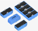
TDK’s xEVCap dc link
capacitor design. |
A Standardized And Modular DC Link Capacitor Design For xEV Traction Inverters
 Photo: Dc link capacitor designs for traction inverters are traditionally fully customized, making the development time-consuming and practical only for large quantities. With the scalable and modular xEVCap, TDK can help inverter designers meet varying capacitance and current requirements at lower volumes while saving time to market. Photo: Dc link capacitor designs for traction inverters are traditionally fully customized, making the development time-consuming and practical only for large quantities. With the scalable and modular xEVCap, TDK can help inverter designers meet varying capacitance and current requirements at lower volumes while saving time to market.
See the full story…
|

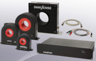
Danisense’s DS, DM and DL
series current transducers. |
Current Transducers With Voltage Output Simplify Measurement In DAQ Systems
 Photo: These transducers simplify the work of design engineers with DAQ systems by integrating the burden resistor, mitigating the risk of miscalculations. They are well suited for a wide range of applications, particularly in harsh environments and high-temperature settings such as e-mobility, solar and wind energy sectors. Photo: These transducers simplify the work of design engineers with DAQ systems by integrating the burden resistor, mitigating the risk of miscalculations. They are well suited for a wide range of applications, particularly in harsh environments and high-temperature settings such as e-mobility, solar and wind energy sectors.
See the full story…
|



Navitas Semiconductor’s GaNSlim ICs. |
GaN Power ICs Drive Ease-Of-Use, Lower System Cost And Energy Savings
 Photo: The latest generation of the company’s GaN power ICs integrates drive, control, and protection, with EMI control and lossless current sensing, all within a high-thermal-performance, proprietary DPAK-4L package. It targets mobile, consumer and home appliance applications under 500 W. Photo: The latest generation of the company’s GaN power ICs integrates drive, control, and protection, with EMI control and lossless current sensing, all within a high-thermal-performance, proprietary DPAK-4L package. It targets mobile, consumer and home appliance applications under 500 W.
See the full story…
|

|







|

 |
 |

 |
 |

 |
 |

INDUSTRY EVENT
 |
|
Power Solutions Provider Expands Customer Support With Facility For Testing And Customization
by David G. Morrison, Editor, How2Power.com
On June 25, power supply manufacturer Advanced Energy (AE) held a press event to introduce their Customer Experience Center (CEC) in Sharon, Mass. At this facility, the company offers free test and power supply customization services to both existing customers and potential customers, helping power supply users by performing pre-compliance EMC and safety testing of power supply products or their end systems, and troubleshooting of any subsequent test failures. Meanwhile, at the same facility, AE engineers can provide customization of AE’s power supply products without NRE charges. All of these capabilities serve to speed the customer’s time to market, while building customer relationships. Read the full story …
|

 |
 |

OTHER TOP POWER NEWS
|
|
 Infineon Technologies has announced a breakthrough in handling and processing the thinnest silicon power wafers, with a thickness of only 20 micrometers and a diameter of 300 mm, in a high-scale semiconductor fab. Infineon Technologies has announced a breakthrough in handling and processing the thinnest silicon power wafers, with a thickness of only 20 micrometers and a diameter of 300 mm, in a high-scale semiconductor fab.
 Texas Instruments has announced a massive expansion of its internal GaN manufacturing, increasing capacity 4x, by adding GaN manufacturing at its facility in Aizu, Japan and using the most advanced GaN manufacturing equipment available today. Texas Instruments has announced a massive expansion of its internal GaN manufacturing, increasing capacity 4x, by adding GaN manufacturing at its facility in Aizu, Japan and using the most advanced GaN manufacturing equipment available today.
 Wolfspeed has announced a total of $2.5 billion in funding from various sources, which will aid its investments in next-generation 200-mm technology. Wolfspeed has announced a total of $2.5 billion in funding from various sources, which will aid its investments in next-generation 200-mm technology.


|

 Early bird registration is now open for the conference and professional education seminars at APEC 2025. Early bird registration is now open for the conference and professional education seminars at APEC 2025.
 Advanced Energy Industries has launched its 2025 - 2026 STEM Scholarship Program, which offers a $20,000 grant toward payment of tuition fees. In addition, selected recipients will receive professional mentoring and internship opportunities. Advanced Energy Industries has launched its 2025 - 2026 STEM Scholarship Program, which offers a $20,000 grant toward payment of tuition fees. In addition, selected recipients will receive professional mentoring and internship opportunities.
 For a technical facelift and renovation of its North Area, CERN has selected the DM1200 zero-flux dc current transducer (DCCT) from Danisense for use in the CERN-designed POLARIS power converters. For a technical facelift and renovation of its North Area, CERN has selected the DM1200 zero-flux dc current transducer (DCCT) from Danisense for use in the CERN-designed POLARIS power converters.


 Navitas Semiconductor has announced an 8.5-kW power supply unit, powered by GaN and SiC technologies to achieve 98% efficiency, for next-generation AI and hyperscale data centers. Navitas Semiconductor has announced an 8.5-kW power supply unit, powered by GaN and SiC technologies to achieve 98% efficiency, for next-generation AI and hyperscale data centers.
 Exxelia is expanding its footprint in India with strategic investment in SVM, enhancing its magnetics offering for medical and adding busbars to its power electronics passive components portfolio. Exxelia is expanding its footprint in India with strategic investment in SVM, enhancing its magnetics offering for medical and adding busbars to its power electronics passive components portfolio.

ABOUT THIS NEWSLETTER: Thank you for reading HOW2POWER TODAY.
How2Power sends no more than one e-mail per month to registered users. Continuing your subscription ensures you'll receive future newsletters. Manage Your Subscription
©2020 All rights reserved. www.how2power.com
|
|