|
 |

|
HOW2POWER EXCLUSIVE DESIGN ARTICLES 
|
Estimating Output Current Tolerance Of A Primary–Side-Regulated Constant-Current Flyback Converter (Part 1): The Analytical Model
by Stéphanie Cannenterre, ON Semiconductor, Toulouse, France
The primary-side-regulated (PSR) flyback converter is a popular converter widely used in the LED drive market and in the portable electronic market for travel adapters. In such converters, the output current can be estimated by sensing the current in the primary-side MOSFET. However, what precision on the controlled parameter can be expected with this technique? LED driver manufacturers are usually targeting ±5% at a given input voltage. Using worst-case circuit analysis techniques, this article will detail how to estimate the accuracy of the flyback output current and compare the obtained results against the ±5% target. The first part of this article will introduce an analytical model of the primary-side constant-current flyback control scheme. Subsequent parts of this article will present a Monte Carlo Analysis of the converter output current followed by an extreme value analysis and a sensitivity analysistypes.
Read the full story…
|
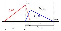
Primary- and secondary-side
currents in a flyback converter
operated in BCM.
|
|
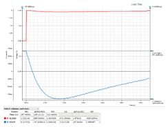
The estimated worst-case error budget is a
sum of the dc accuracy, the output voltage
ripple, and the transient droop (the largest
source of error), which is simulated here. |
Online Simulation Validates Output Error Budget Analysis For Buck Converter
by Brooks Leman, Mark Fortunato and Nazzareno (Reno) Rossetti, Maxim Integrated, San Jose, Calif.
A buck converter design for a particular Maxim customer specified a tight output voltage tolerance across all operating conditions. To ensure the ensuing design met this goal, it was necessary to perform an output voltage error budget analysis. In general, the biggest contributor to the error is the output droop consequent to the load step. However, using different methods to estimate the droop led to different results. How do we make sense of it? In this article, the authors perform a buck converter output error budget analysis. In estimating the droop amplitude, they compare a simulated result with two different back-of-the-envelope estimates and reconcile the different approaches. Read the full story…
|
The Engineer’s Guide To EMI In DC-DC Converters (Part 2): Noise Propagation And Filtering
by Timothy Hegarty, Texas Instruments, Phoenix, Ariz.
High switching frequency is the major catalyst for size reduction in the advancement of power conversion technology. It is essential to understand the EMI characteristics of high-frequency converters since the required EMI filter necessary for regulatory compliance typically occupies a significant portion of the overall system footprint and volume. In part 2 of this series, you’ll gain an insight into dc-dc converter conducted EMI behavior by understanding sources and propagation paths for both the differential mode (DM) and common mode (CM) conducted emissions noise components. DM and CM noise separation from the total noise measurement is described, and a boost converter example is used to highlight the main CM noise conduction paths that exist in an automotive application.
Read the full story…
|
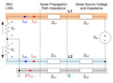
A model of EMI noise generation, propagation,
and measurement for a dc-dc converter.
It also applies to ac-dc converters. |
|
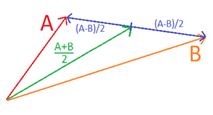
Noise signals A and B can be seen as the combination
of a common-mode noise (A+B)/2 which is the average
of both signals and of a differential-mode noise
(A-B) which is the difference between both. |
EMI For Wisdom Seekers (Part 3): Differential Mode Noise Versus Common Mode Noise
by Patrice Lethellier, Noizgon, Salt Lake City, Utah
Having discussed why designers of power supply packaging need an understanding of electromagnetic interference (EMI) and provided a practical introduction to the topic in the parts 1 and 2, we now introduce the concepts of differential noise and common-mode noise. These two sources of EMI have different causes and different treatments. Read the full story…
|
|  |
FOCUS ON MAGNETICS
Sponsored by Payton Planar Magnetics
A monthly column presenting information on power magnetics design, products, or related technology |
Transformer Design (Part 1): Maximizing Core Utilization
In this article, the utilization of the core in transformer design is considered by reviewing earlier work on the optimal turns that maximize use of the core in the magnetic part of coupled-inductor design. Important differences between coupled inductor and transformer design are identified and different criteria are derived for making the same maximum use of a transformer core, and for the kind of application that can make it worthwhile. Read the full story…
|
|
|
 |
SPOTLIGHT ON SAFETY & COMPLIANCE
Sponsored by Power Integrations
A monthly column discussing standards and regulatory requirements affecting power electronics |
A Power Supply Can’t Fix All EMC Woes, Yet Partnering With The Right Power Supply Experts Early Can
by Kevin Parmenter, Chair, and James Spangler, Co-chair, PSMA Safety and Compliance Committee
Recently I was called by a customer who was failing EMC in the test lab. They were using one of our competitor’s power supplies and we had been talking with them about using ours because of its superior value and performance. It was hard to ascertain if our pitch was falling on deaf ears or not. But now, with their product failing compliance testing, suddenly we were important to them as evidenced by them calling me after hours. The discussion went something like “does your power supply have lower EMC than the one I’m now using?” Of course they were talking about radiated EMC as I already had helped them with selecting a line filter, which was sufficient to make sure either power supply would pass conducted EMC. With their product in the test lab there was real urgency as the money meter was running with the test lab charging them by the hour as the customer tried to get their product to pass EMC. This is their story and the lessons learned. Read the full story…
|
|
|
 |
|
|
|
|
 — POWER PRODUCTS IN 3 IMAGES OR LESS — POWER PRODUCTS IN 3 IMAGES OR LESS
|
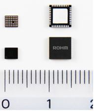
ROHM’s BD99954GW/MWV
dual-input boost-buck charging ICs. |
Dual-Mode Battery Charge ICs Enable Simultaneous USB PD And Wireless Charging
 Photo: The dual-input boost-buck charging ICs generate a charging voltage for one to four cells through boost-buck control for USB Power Delivery. They also support USB BC 1.2. This facilitates configuration of dual-mode systems capable of simultaneous charging via USBPD, wirelessly, or from an ac adapter. Photo: The dual-input boost-buck charging ICs generate a charging voltage for one to four cells through boost-buck control for USB Power Delivery. They also support USB BC 1.2. This facilitates configuration of dual-mode systems capable of simultaneous charging via USBPD, wirelessly, or from an ac adapter.
Diagram: In ROHM’s two-input charging system, a built-in charging adapter discrimination function enables automatic switching between modes without an MCU. This eliminates the need to mount and adjust external peripheral components such as transistors and resistors typically necessary for each charging system.
More details… |
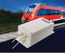
ABSOPULSE Electronics’ RSI 30-D1
series railway quality sinewave inverters. |
30-VA Railway Sinewave Inverters Feature IP66 Protection
Photo: Installed in IP66-rated waterproof, die cast aluminum packages with sealed connectors, these railway quality sinewave inverters are protected from the ingress of rain, humidity, sand, dust, metallic dust, oil and other contaminants. They meet the requirements of EN50155 for electronic equipment used on railway rolling stock and various other standards.
More details… |

SynQor’s UPS-1500-S-2S
Shallow Depth Military-Grade UPS.
|
Military-Grade UPS Delivers High Performance In Shallow Depth
Photo: The UPS delivers 1250 W (1500 VA) of output power in a 2U high unit that is 17 in. wide x 13.6 in deep. The UPS specifies >10 minutes run-time at full power. It weighs 33 lbs including the lithium polymer battery pack.
More details… |
|
 |
|
 |
OTHER TOP POWER NEWS
|
|
The PSMA and IEEE PELS are jointly sponsoring the third high-frequency magnetics workshop, “Power Magnetics @ High Frequency – Eliminating the Smoke and Mirrors,” on Saturday, March 3, 2018, the day before and in the same venue as APEC 2018 in San Antonio, Texas. If you’ve not attended this session before, read Bob White’s excellent recap of last year’s workshop. PSMA/PELS are also sponsoring a “Capacitors in Power Electronics Workshop”.
Also APEC related, Christophe Basso will be presenting a professional education seminar on "Closing the Loop through Simulation and Analysis" on Monday morning, March 5. .
ON Semiconductor has joined the global Charging Interface Initiative e.V. (CharIN) ecosystem with the goal of promoting standards for charging systems in electric vehicles (EVs), and more..
Powercast has launched an FCC-approved far field (up to 80 ft) wireless charger for consumer devices.
|
|
 |
|
 |
IN MEMORIAM… |
|
Myron Miller, pioneer in power electronics publishing and conferences, passed away last month at age 89. In 1975, Miller founded Solid State Power Conversion magazine, which later became Power Conversion and Intelligent Motion, then PCIM Power Electronic Systems, and finally Power Electronics Technology. Miller also founded the ground breaking Powercon and High Frequency Power Conversion conferences among others. To read Sam Davis’ informative bio of Myron Miller, click here.
On the occasion of Power Electronics Technology’s 30th anniversary, Miller contributed a column discussing the history of the publication and conferences he launched. To read this column, see “Thanks for the Memories and Support”.
|
|


|
|